While today's cars have a lot of bells and whistles, you can be a bit hard pressed to find all the features that you want in your vehicle (at least not without blowing your budget).
This project was born from a need to address a couple of features that I wanted to have in my truck.
The first feature was to have an electronic compass to serve as a companion to my 2 meter amateur radio rig. As a severe storm spotter, knowing what the direction is of the weather that I'm observing is essential for when I need to radio in my reports.
The second feature is more along the lines of creature comforts. Many vehicles these days have an outside temperature read out feature, however you very rarely find one that will display what the temperature is inside the vehicle. I always wanted to know what the actual temperature is in the car when I'm driving (and it's a great help in solving those age old debates that you sometimes have with your passengers on whether it's "too hot" or "too cold" )
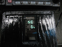 It's from these two needs that an inspiration hit during my last trip to my local U-pick auto parts place. There it dawned on me that a good number of vehicles these days contain electronic compasses and external temperature displays.
By utilizing one of these displays, I determined that I would probably be able to build a standalone compass and interior thermometer. As an added bonus I wanted to it built in such a way that it could be be easily moved from car to car (or really to any "mobile" object, like a boat for example).
Step 1: Finding the Donor
Compass and outside temperature displays are actually fairly common features that are found installed in the center overhead consoles in many minivans that have been produced over the past couple of decades. The unfortunate thing about those particular temperature displays is that often the outside temperature sensor is fed into the vehicle's' ECM module where it's used to provide input for other vehicle functions (like running the cooling fans) with the console reading the outside temperature data from the ECM. I considered this to be a bit too complex of a thing to tackle for what I had in mind.
There are however a number of vehicles that utilize the rear view mirror to display the compass heading and outside temperature. These mirrors, generally manufactured by Gentex, are more commonly found in GM SUV's.
 These displays are directly connected to their own dedicated outside temperature sensors and have their compass modules enclosed in a small plastic housing attached to the mirror. This arrangement made these the perfect candidate for my compass and interior thermometer project.
 In the case of my local auto wrecker's yard, I found a number of early to mid 2000's Saturn Vue's that had this type of mirror installed. Removing the mirror is a fairly straight forward exercise. The mirror is attached to the windshield via a connector that is glued onto the windshield itself. The mirror is attached to this connector with a hex nut. To remove the mirror, simply use an Allen wrench to remove the hex nut and the mirror should detach from the windshield (Alternatively, you can also remove the mirror from the windshield by carefully prying it off the windshield with a thin screwdriver).
 Once the mirror is off the windshield, cut the wires that run from the mirror to the headliner - make sure to cut the wires close to the headliner in order to allow yourself some wire to work with later on.
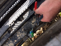
The outside temperature sensor that is used by the mirror is located in front of the radiator of the vehicle and is attached in the middle of the bottom radiator mount. To get at the sensor, you need to remove the top part of the front grill of the vehicle to expose the front of the radiator. In the case of the Vue, this means removing 2 plastic speed nuts in the center of the grill and pulling back on it to expose the radiator and the sensor.
The sensor itself is also attached to the radiator support by a plastic speed nut. To remove the sensor, Remove the speed nut by gently prying up on it with a flat screwdriver until the sensor is free. Once the sensor is free, cut the wire that is attached to the sensor (again, make sure to leave some wire attached to the sensor for later on).
Step 2: Gathering the Parts
After the trip to the junkyard, you should have the following pieces:
- The rear view mirror
- The compass sensor (Attached to the windshield mount for the mirror)
- Wiring harness for the mirror
- Outside temperature sensor (including wiring harness for the sensor)
Before we go any farther, now would be the time to do a quick "smoke test" to ensure to that the mirror and the temperature probe are working as expected - After all we did get our parts from a junkyard.
The wiring harness for our mirror has 5 wires:
- A Yellow wire - which is the the 12 Volt Positive wire
- A Black wire which is the 12 Volt Ground wire
- A Light Green wire which is used for back up lamps - we will not be using this wire
- A Light Green with Black Stripe wire which is used for the temperature probe
- A Grey wire which is used for the temperature probe
 To test the mirror, connect the wires for temperature sensor on the wiring harness to the temperature sensor (the wires connected to the sensor will match the color of the wires on the wiring harness - so connect Grey to Grey and Light Green/Black to Light Green/Black). Connect the black and yellow wires to a 12 volt power source. The compass display in the mirror should light up and the temperature display should display a reasonable temperature reading.
 Now that we've confirmed that the compass and temperature sensor are working, the next step is to liberate the brains of the compass from the mirror. With this mirror. the compass sensor is located in a small plastic pod that's located at the point where the mirror connects to the windshield. To remove the compass sensor, you just need to separate the plastic shell that contains the sensor by carefully prying open the shell at its seam with a fine edged screwdriver. Be careful to not to damage the wire that connects the compass sensor to the mirror.
Unplug the wiring harness from the mirror by depressing the tab on the plug that's attached to the wiring harness and pulling it out of the mirror. Once the wiring harness is removed, remove the plastic wrapper that is covering the wires on the harness. Cut the Light Green wire (not the Light Green with Black Stripe wire) at the base of the wiring harness plug.
The wire to the compass sensor can be left plugged into the display circuit board
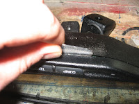 Next remove the compass and temperature display from the mirror. Similar to the plastic pod for the compass, the display can be removed by carefully (Remember - Seven years bad luck if you break the mirror!) separating the mirror housing along the it's seam with a fine edged screwdriver. Once the mirror housing is apart, the display circuit board just simply pops out.
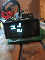 Once the display circuit board is free from the mirror, carefully bend the LED display on the circuit board so that it's at 90 degree angle to the board. Once the display is bent, it would be a good idea at this point to do another smoke test by reconnecting the display circuit board to the 12 Volt power source and making sure that the display is still working properly.
 Now that the display circuit board and compass sensor are prepared. The next step is to get the temperature sensor ready. The sensor is housed in a plastic mounting bracket that was used to attach the sensor to the vehicle. The sensor is held in the mounting bracket with a few plastic tabs. To remove the sensor, simply push back on the tabs that are holding the sensor in the bracket with a flat screwdriver until the probe pops out of the housing
 At this point we should now have all the various parts that we've collected from our vehicle ready for the next step. One last thing we need to do before moving on is to obtain a power socket that will be used to connect to our compass/thermometer to a power source and a car power cable that will fit the typical car power socket (or for us old school types, the cigarette lighter socket).
Step 3: Building the Case - Cutting the Sides
The next step is to construct a case for the compass/thermometer. Based on the measurements of the display circuit board that's being used, I needed to build something that would be roughly 3 inches high, 3 inches wide and about 7.5 inches long.
While you could try different case configurations based on your particular needs, since I was going to have the compass/thermometer as a companion for my 2 meter radio, I determined that a simple "box" which would sit on the floor of my truck beside my radio would be the best solution for what I wanted to accomplish..
To build the case, you need the following:
Materials:
- 4 pieces of 3.5" X 7.5" 1/2 inch plywood for the sides of the case
- 2 pieces of 3" X 3.5" 1/2 inch plywood for the front and back of the case
- Wood Glue
- 1 inch finishing brad nails
- Paint
- 12 Volt Power socket - I picked mine up at my local surplus store - but you can pick them up at any electronics supplier
- 12 volt automotive power cable with connector to match the power socket
Tools:
- Table saw
- Miter saw
- Scroll saw
- Drill with a 1/2 inch and 1/4 inch drill bit
- Hot Glue Gun and Glue Sticks
- Soldering iron and solder
- Router and router table with a 3/4 inch straight router bit
- Nail gun (air powered preferred)
- Clamps


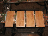
Start by making the sides of the case. Using a 3.5 inch by 30 inch section of 1/2 inch plywood (You can this piece of wood from a larger piece of plywood by using a table saw if required), cut out four 7.5" pieces of plywood with a miter saw.
Once you have your four 3.5" X 7.5" plywood sides cut, Set up your router with a 3/4 inch straight bit. Set the router depth so that the bit will cut a 1/4 inch X 1/4 inch edge. Once you have set the router to cut at the correct depth, Cut a 1/4 inch X 1/4 inch groove along all edges of the four plywood pieces (A word to the wise - make sure you cut the 4 grooves on the same side of the plywood!)
By cutting these grooves along the edges, you are actually creating half lap joints that will be used to assemble the case later on. The main reason that I chose this method was that I wanted the joints for the case to be as simple but as strong as possible (If you don't have a router, or if you rather go much more simpler, a simple butt joint will work fine too).
Test fit the sides by assembling the 4 sides together into a box. The grooves should interlock together to make tight fitting joints.
Please take note of the cutting and routing diagrams in the photos above, we will also be referring to them in future steps.
Step 4: Start Building the Case
 While test fitting the four sides of the case, take a moment to give the display circuit board a quick test fit inside the case. At this point the display circuit board should be slightly taller (by about a 1/2 inch or so) than the case. The length of the display circuit board should fit nicely within the case.
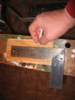 The reason why the case is slightly less taller than the circuit board is that we want to have the inside of the case act as a secured mounting point for the display circuit board.
 To get some guidance on how this will be done, just refer to the routing diagram in the previous step, (but never fear - we'll walk through the steps on mounting the circuit board)
 To create the mounting points for the display circuit board, take top and bottom plywood pieces of the case and mark a line on the interior side of the pieces one inch in from the inside left hand edge of the.plywood pieces.
With a table saw, set your blade depth to 1/4 inch and set your saw fence to be 1 inch in from the blade. Cut a 1/4 inch deep groove on the top and bottom pieces of the case along the the lines that you've just marked.
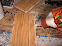 Next, take the bottom part of the case (that now has the 1/4 inch groove cut into it) and attach the 2 side pieces of the case to it by using wood glue and the one inch brad nails, If necessary, clamp the sides to the bottom in order to make sure you have a nice tight joint.
 Once the the glue has dried, give the display circuit board a another test fit in the partially assembled case. When doing the test fit, make sure that the groove in the case bottom is on the left side of the bottom (when viewing the case from the front). The bottom of the display circuit board should fit snugly in the groove in the bottom of the case.
Step 5: Creating the Front of the Case
 Next, take the two 3" X 3.5" pieces of 1/2 inch plywood (which will serve as the front and back of the case), With a table saw, set your blade depth to 1/4 inch and set your saw fence to be 1 inch in from the blade. Cut a 1/4 inch deep groove on the back piece for the case.
After that, use the router to cut a 1/4 inch X 1/4 inch edge along the four sides of both plywood pieces (this would be similar to what was done for the side, top and bottom pieces in the previous steps).
 Once the edges have been routed, the next step is to build out the front panel for the case. Do another test fit of the circuit board and LED display for the compass into the case and attach the front of the case to the sides and bottom of the case. Mark out the outline of the LED display on the front of the case with a pencil. With our particular compass from our Saturn Vue, we need an opening in the front of our case that is 1.25 inches by 2 inches in size in order for the LED display to fit through. If you don't feel like testing fitting the display board and marking out the case front, you can refer to the cutting diagram for the front display that's been provided in Step 3.
Once you have the opening for the display marked out, cut the opening out of the front of the case with a scroll saw. Make sure to give the opening a test fit with the LED display and make any required adjustments so that the display can snugly fit the opening.
 In order for the display to be flush to the outside of the case, we will need to make a small groove to the right (looking from the inside of the case) of the display opening in order allow some room for the display circuit board. Using the router with the 3/4 inch straight bit again, cut a 1/2 inch groove to the right of the opening (Again, you can refer to the routing diagram in Step 3 for additional details). The groove should be about a 1/4 inch deep. Test fit the display again in the opening to make sure that the display is flush to the front of the case - if not, cut the groove a little deeper with the router until the display is flush with the outside of the case..
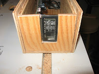
Step 6: Creating the Back of the Case
We now focus our attention on the back part of the case.
 In order to allow for clearance for some components that are mounted at the rear of the display circuit board, a 3/4 inch slot needs to be put into the back of the case.
 To create the expanded slot, use the router and the 3/4 inch straight bit one more time and make a 3/4 inch groove that is just to the right of the 1/4 inch groove that's been cut into the plywood Make sure that the groove is no more than 1/4 inch deep.
Once the groove has been cut, do a final test fit of the display circuit board in the case. With the front and back plywood pieces of the case installed The circuit board should fit snugly into the slots that have been cut into the front and the back pieces.
 Likewise the front and back pieces of the case should join tightly with the rest of the case.
Step 7: Creating the Top of the Case
Now on to the final part of the case - The top!
In a previous step we had put in a 1/4 inch groove in the inside of top of the case. However during a test fit with the display circuit board I noticed that some additional clearance is needed in the top to allow access for the power connector on the circuit board.
 To add this clearance we use our trusty router and 3/4 straight bit for one last time. Starting at the "rear" of the case top, cut a 3/4 inch groove 1/4 inch deep just to the left of the 1/4 groove in the top of the case. The groove should be at least 5 inches long (However if it's easier for you, the groove can also run the entire length of the case top.
 Once the 3/4 inch groove is cut. put the display circuit board back into the case again and do a final test fit with the top of the case seated into case body. The top should seat tightly with sides of the case and the circuit board should seat firmly in the the grooves in the top and
 bottom of the case.
Step 8: Putting It Together
Now that we have all of our parts of the case cut and configured so that the display circuit board can live happily inside it, it's now to put everything together.
To assemble the case, start by attaching the front and back of the case to the main body of the case . Attach the front and back by applying a little bit of wood glue along the inside grooved edges of the bottom and sides of the case on both the front and back ends of the case body. Firmly seat the front and back pieces into the case body. Make sure that the grooves that you routed in the front and back pieces for the display circuit board line up with the groove that you cut in the bottom of the case. Also make sure that the opening that you cut for the LED display on the front piece is pointed towards the top of the case.
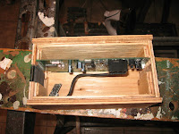 Clamp the all the pieces together to ensure a tight fit and let the glue dry,.
Once the glue has dried, it's probably wouldn't be a bad idea to give the display circuit board one last fitting to ensure that it fits properly in the case (if you need to make any fine adjustments at this point, you can make them by using with some course sandpaper)

On the right side of the case, drill a 1/4 inch hole towards the back end of the case, near the bottom of the case. This hole will used as the access port for the power connector for the display circuit board.
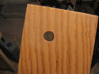 On the top of the case, drill a 1/2 inch hole towards the right front corner of the the top. Make sure that your hole is at least 1 inch from the edges of the case top and that it does not interfere with the groove that has been cut in the top. This hole will server as the outside access for the temperature sensor..
 Now that the case has been assembled, paint the exterior of the case in the color of your choice (Remember to keep the top of the case separated from rest of the case for now)
Step 9: Installing the Display Circuit Board
Now that the case is all assembled and painted, the time has come to permanently install the display circuit board.,
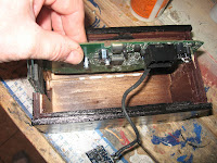 Start by running a bead of wood glue along the groove at the bottom of the case. Once the glue has been applied, insert the display circuit board into the case and firmly seated into the groove at the bottom of the case.
 Next adjust the LED display so that the front of the LED is flush with the exterior of the case. Using hot glue, secure the LED display to the front of the case.
 Next secure the rear of the circuit board to the back of the case with hot glue. Make sure the the circuit board is placed into the groove that's been cut into the back of the case and that it is glued as tightly as possible to the left hand side of the groove.
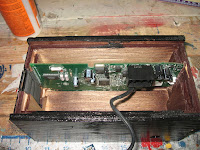
The display board is now installed in the case. Allow the glue to dry fully before moving to the next step.
Step 10: Wiring It Up
It's now time to connect the various components together to the wiring harness.
The first step is to wire up the power connections. Taking the 12 Volt power socket, connect the yellow wire on the wiring harness to the positive terminal of the socket followed by connecting the black wire on the wiring harness to the negative terminal of the socket.
 Next connect the temperature sensor to the wiring harness. This is done by connecting the Light Green with Black Stripe wire on the wiring harness to the Light Green with Black Stripe wire on the temperature sensor. Likewise connect the Grey wire on the wiring harness to the Grey wire that's attached to the temperature sensor. Solder the wires that are connected to the temperature sensor and seal the solder joints with electrical tape or shrink tubing.
After all the wiring connections are done, mount the 12 Volt Power socket into the case. Apply some hot glue to the outside of the power socket (make sure not to get any hot glue inside the the electrical connections of the socket). and insert the power socket into the 1/4 inch hole that we previously into the side of case.


Plug the plastic connector of the wiring harness into the display circuit board and we are all wired up!
Step 11: Installing the Compass Module
Now that the display circuit board secured into the case, we now need to attach the compass sensor to the case.
Where you place the sensor within the case will depend on how the compass/thermometer is going to be mounted in the vehicle. For the compass sensor to read properly, the sensor circuit board needs to situated horizontal to the ground, with the end of the sensor that not have the cable that goes to the display circuit board connected to it pointed in the direction that you would be traveling (or inversely, the end of the sensor that has the cable attached would be pointing to the rear of the vehicle)
In my case, the compass/thermometer is going to be located on the floor of my truck with the display pointing upwards. So as a result, the compass sensor is going to be attached to the back of the case, with the side of the sensor that has the cable connection pointing towards the bottom of the case (or to confuse further... pointing towards the rear of the truck :) ).
If your compass/thermometer is going to be sitting on top of your dashboard, you would need to place the sensor to the bottom of the case with the side of the sensor that has the cable connector pointing towards the LED display.
Once you've determined where to place the sensor, secure the sensor to the case with some hot glue.
Step 12: Attaching the Temperature Sensor
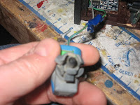 We next need to attach the temperature sensor to the top of the case. The probe end of the sensor should be able to snugly fit into the 1/2 hole that has been drilled into the top of the case.
Therefore, installation of the sensor is very straight forward. Just insert the probe end of the sensor into the hole and secure it with a bit of hot glue.
Once the glue has dried on the sensor, fit the top of the case onto the body of the case
In order to allow for future access to the display board if any future adjustments are needed (you'll see why in the next step), do not glue the top onto the case. The top should fit snugly into the case without any fasteners, however if the top doesn't fit very snugly, you can always use double sided tape to secure the top.
The junkyard compass/thermometer is now assembled and ready to try out!
Step 13: Vehicle Installation and Calibrating the Compass
Take the compass/thermometer out to your vehicle and plug in the 12 Volt cable into the compass/thermometer and into the 12 Volt power socket of your vehicle. Make sure that you power being applied to the socket.
The LED display should light up and show a "meaningful" compass heading and temperature. At this point we should do a calibration of the compass in order to make sure that the compass is as accurate as possible.
 With the compass/thermometer still powered on, carefully remove the top of the case. At the bottom of the left side of the display circuit board there will be two small push switches. Using a pencil or screwdriver, press and hold the switch that is nearest to the back of the case. Release the switch when the word "CAL" is displayed on the LED screen. Replace the top of the case and place the compass/thermometer to its permanent location in your vehicle.
The compass is now in calibration mode. The easiest way to calibrate the compass is to basically just go for a drive. When driving, make sure to make one or two circles, usually a couple of drives around the block will do it. Keep in mind - very tight circles won't work (So... No donuts in a parking lot!). The idea is that you want to point to all points of the compass.
 Continue driving until "CAL" is no longer displayed in the LED. Your compass should now be calibrated. As a double check you can always use another compass or a GPS to confirm that the compass/thermometer is displaying correctly
Step 14: Time to Hit the Road
The compass is now ready to point you in the right direction while at the same time letting you know exactly how hot (or cold) you are.
In my case the compass/thermometer compliments my 2 meter amateur radio rig quite nicely. However the nice thing is that since that it is completely portable, it can be easily moved from location to location. So for example, when I'm not storm spotting, this will be quite a handy accessory to have in the boat this summer while I'm out fishing.
Why not give it a try for yourself and never be truly lost again!






No comments:
Post a Comment