During my time as an amateur radio operator, I've had the opportunity to get my hands on a number of "old school" radios that utilize vacuum tubes instead of transistors (surprisingly, a fair bit of amateur radio equipment were still manufactured with vacuum tubes until the late 1970's / early 1980's).
While vacuum tubes have many advantages (some people swear by the sound quality of a radio that uses vacuum tubes), vacuum tubes do eventually burn out.
Over a period of time, I've managed to collect a number of burnt out vacuum tubes.
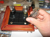
Instead of throwing them out, I've found that there is a certain degree of elegance in the construction of a vacuum tube that make me want to try and showcase them somehow.
The inspiration for this project finally arrived with a trip home from work one day. In my area there are a large number of Mennonite craftsmen that build fine wood furniture. Often they will sell their wood scraps as camp fire wood. It was on this particular trip home that I stopped at one of these places and picked up a bag of wood scraps for my backyard fire pit.
When I got home I noticed that the bag was full of various lengths of highly finished red cedar. I was immediately struck on how beautiful the wood was. Immediately, I abandoned my campfire idea, since I now finally found a way to show off my vacuum tubes.
With this project, I also wanted to give the tubes the look of "glowing" as they would when they were in use. To create this effect, I used a solar rechargeable circuit to drive flickering red LED's which are installed in the base of the tubes.
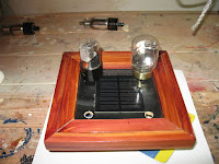
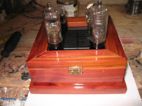
In the end I ended up with a beautiful display of an older technology that still gives that warm flickering glow at night.
Step 1: What's Needed to Build This
This project can be broken down to 2 major components:
- The cedar display case
- A "hand built" solar powered lighting circuit.
Most of the components can be sourced from Digikey.ca but you would need to order the Flickering LED's from PCBoard.ca
To make the vacuum tube display, you need to gather the following items:
Electronic Components:
- Four "expired" vacuum tubes
- One 2"x2" perf board - I got mine at my local surplus store
- One Solar Cell (400mW 4.6V) - Digikey part number 1471-1517-ND
- One Photocell - Digikey part number PDV-P8104-ND
- One 2N3904 transistor - Digikey part number 2N3904FS-ND
- Four Flickering LED's - Red - PCBoard.ca part number RC259-07
- Two 100 Kilo Ohm resisters - I got mine from PCBoard.ca
- One 1N4006 Diode - I also got this from PCBoard.ca
- Black and red hook up wire
- One 2 AA battery box - I also picked this up at my local surplus store.
- 2 AA rechargeable batteries
Materials
- 6.25 inch X 6.25 inch piece of 1/2 inch Red Cedar - for the bottom of the case
- 14 inch X 6.5 inch piece of 1/2 inch Red Cedar - for the bottom sides and lid of the case
- 7 inch X 4 inch piece of 1/2 inch Red Cedar - for the bottom trim of the case
- 5 inch X 5 inch piece of 1/4 inch plywood - painted black
- Two 1 inch brass hinges
- One small brass clasp
- Spar Varnish - any clear varnish is fine - but I like the look that Spar Varnish gives
- Steel Wool
- Paint Brush
- Wood Glue and hot glue sticks
Tools
- Miter Saw
- Router with a 1/2 inch straight bit
- Table Saw
- Drill Press with 1/4 inch drill bit and 1.5 inch drill bit
- Variable speed drill or rotary tool with 5mm drill bit
- Pliers
- Soldering iron and solder
- Four 3 inch corner clamps
- Hot glue gun
- Square or Ruler
- Wire Strippers
- Optional - Multi meter
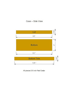
To build the case, first start out by cutting out the following pieces from 1/2 inch red cedar with the table saw:
- Four - 2" X 6.5" pieces for the case bottom sides
- Four - 0.75" X 6.5" pieces for the lid sides
- Four - 0.75 X 5.75" pieces for the lid top
- One - 5.75" X 5.75" piece for the case bottom
- Four - 0.75 X 7.25" pieces for the case bottom trim
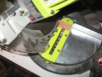
With the base pieces cut out, do the next cuts with a miter saw
For the case bottom sides, cut a 45 degree angle on each end, making sure that the 45 degree angle is along the 1/2 inch side of the piece. Also make sure that the angles on each end are such that the "long" side on the angle are on the same side of the wood piece.
For the case lid sides, cut a 45 degree angle on each end, making sure that the 45 degree angle is along the 1/2 inch side of the piece. Also make sure the angles on each end are such that the "long" side on the angle are on the same side of the wood piece.
For the lid top pieces, cut a 45 degree angle on each end, making sure that the 45 degree angle is along the 3/4 inch side of the piece. Also make sure the angles on each end are such that the "long" side on the angle are on the same side of the wood piece.
For the case bottom trim, cut a 45 degree angle on each making sure that the 45 degree angle is along the 3/4 inch side of the piece. Also make sure the angles on each end are such that the "long" side on the angle are on the same side of the wood piece.
For further details, please refer the to cutting diagrams.
Step 3: Building the Lid Side Assembly
To build the lid for the case, first start by assembling the sides of the lid.
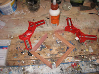
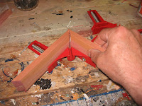
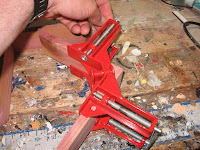
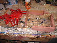
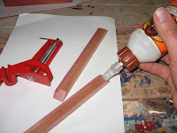
To assemble the lid sides, the easiest approach is to build it as two separate "half" pieces. Start by taking 2 of the 0.75" x 6.5" red cedar lid side pieces and a 3 inch corner clamp. Do a dry fit of the 2 pieces by joining a corner of the 2 pieces together at a one of the 45 degree joint ends. You want to make sure that the two 45 degree corners will make a 90 angle when they are joined together.
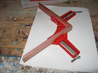
When you have confirmed the joint fit, apply a dab of wood glue on the 45 degree ends that you will be joining together and clamp the 2 pieces into the corner clamp, making sure that the glued ends make a nice tight join in the clamp.
With other 2 pieces of the lid side, do the same process again and gluing the two 45 degree ends together in a second corner clamp.
Allow the glue to dry and remove the lid pieces from the clamps
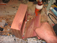
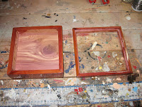
At this point you should have 2 half squares. To complete the lid side assembly, apply a dab of glue to the 'unconnected" 45 degree ends of the 2 half squares and attach the 2 pieces together so that the 2 halves form a complete square. Clamp the glued ends with 2 corner clamps (one for each glued end) and allow the glue to dry.
Remove the clamps and the lid side assembly is complete.
Step 4: Build the Lid Insert
In order to give the case lid a bit more pizzazz, I found that a red cedar inlay on the top of the lid really adds to the overall appeal of the case.
To assemble the lid insert, the easiest approach is to follow the same approach that we did for the lid sides and build it as two separate "half" pieces.
Start by taking 2 of the 0.75" x 5.75" lid insert pieces and a 3 inch corner clamp. Do a dry fit of the 2 pieces by joining a corner of the 2 pieces together at a one of the 45 degree joint ends. You want to make sure that the two 45 degree corners will make a 90 angle when they are joined together.
When you have confirmed the joint fit, apply a dab of wood glue on the 45 degree ends that you will be joining together and clamp the 2 pieces into the corner clamp, making sure that the glued ends make a nice tight join in the clamp.
With other 2 pieces of the lid insert, do the same process again, gluing the two 45 degree ends together in a second corner clamp.
Allow the glue to dry and remove the insert pieces from the clamps At this point you should have 2 half squares.
To complete the lid insert assembly, apply a dab of glue to the 'unconnected" 45 degree ends of the 2 half squares and attach the 2 pieces together so that the 2 halves form a complete square. Clamp the glued ends with 2 corner clamps (one for each glued end) and allow the glue to dry. Remove the clamps and the lid insert assembly is complete.
Step 5: Completing the Lid
To complete the lid, the lid insert needs to be attached to the lid side assembly
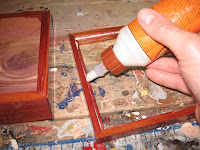
To attach the lid insert to the lid sides, apply a small bit of glue to the top inside edge of the lid side assembly.
The lid insert should then be attached to the lid side assembly by placing the insert assembly inside the lid side assembly.
Make sure that the lid insert is flush with the top of the lid side assembly.
Allow the glue to dry overnight.
Step 6: Building the Case Bottom
With the top of the display case taken care of (for now), it's now time to focus on the bottom half of the case.
To start with the bottom, we need to assemble the bottom sides of the case. Once again, the easiest approach in assembling the sides is is to follow the same approach that we did in the previous steps and build it as two separate half pieces. Start by taking 2 of the 2" x 6.5" red cedar side pieces and two 3 inch corner clamps. Do a dry fit of the 2 pieces by joining a corner of the 2 pieces together at a one of the 45 degree joint ends. You want to make sure that the two 45 degree corners will make a 90 angle when they are joined together.
When you have confirmed the joint fit, apply a dab of wood glue on the 45 degree ends that you will be joining together and clamp the 2 pieces with the 2 corner clamps (one clamp at the top and one clamp at the bottom of the joint). Make sure that the glued ends make a nice tight join in the clamps.
With other two 2" X 6.5" side pieces, do the same process again, gluing the two 45 degree ends together in a second set of corner clamps. Allow the glue to dry and remove the side pieces from the clamps.
At this point you should have 2 half squares. To complete the bottom sides assembly, apply a dab of glue to the 'unconnected" 45 degree ends of the 2 half squares and attach the 2 pieces together so that the 2 halves form a complete square. Clamp the glued ends with 4 corner clamps (2 clamps for each glued end) and allow the glue to dry.
Remove the clamps and the case bottom sides assembly is complete.
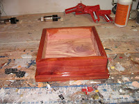
Apply a small bit of glue to the bottom inside edge of the case bottom side assembly. Take the 5.75" X 5.75" inch bottom piece of red cedar and attach it to the bottom of the case side assembly. Make sure that the bottom piece is flush with the bottom of the side assembly.
Allow the glue to dry overnight.
Step 7: Varnishing the Case
Now that the major components of the display is now assembled, now would be a good time to give the case a good coat of stain or varnish.
You can stain the case to any color of your choice, however since I really like the look of red cedar, I decided to give the case 2 coats of spar varnish in order to highlight the natural color and patterns of the wood.
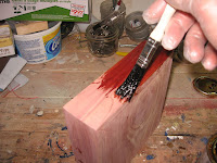
Apply the varnish in light coats with a soft bristle brush. After each coat of varnish has dried, give the case a light sanding with steel wool in order to make sure that the surface of the case is as smooth as possible.
Step 8: Adding the Bottom Trim
To give the bottom of the case a more decorative flair, I added a bottom base for the case, also made out of red cedar.
To create the bottom trim, take the four 0.75 X 7.25" pieces red cedar, and with the router table and half inch straight bit, add a 1/4 inch by 1/4 inch groove along one side of each of the red cedar pieces.
Once the grooves are made, using the miter saw, cut a 45 degree angle on both end of the trim pieces.
When cutting the angles, make sure that the angles are cut so that the "short' end of the angles are on the same side that the grooves were cut.
To assemble the trim pieces, we will use the same approach that we did in the previous steps and build it as two separate half pieces. Start by taking 2 of the trim pieces and a 3 inch corner clamp.
Do a dry fit of the 2 pieces by joining a corner of the 2 pieces together at a one of the 45 degree joint ends. You want to make sure that the two 45 degree corners will make a 90 angle when they are joined together. Make sure when you are joining the pieces together, that the grooves in the trim pieces almost meet together.
When you have confirmed the joint fit, apply a dab of wood glue on the 45 degree ends that you will be joining together and clamp the 2 pieces into the corner clamp making sure that the glued ends make a nice tight join in the clamp.
With other two trim pieces, do the same process again and glue the two 45 degree ends together in a second corner clamp. Allow the glue to dry and remove the side pieces from the clamps.
At this point you should have 2 half squares. To complete the trim assembly, apply a dab of glue to the 'unconnected" 45 degree ends of the 2 half squares and attach the 2 pieces together so that the 2 halves form a complete square.
Again make sure that the grooves in the trim pieces also meet at the joints.
Clamp the glued ends with corner clamps and allow the glue to dry. Remove the clamps and the case trim assembly is complete.
Apply a couple of coats of spar varnish to the trim assembly and allow the varnish to dry. Make sure to lightly sand the assembly with steel wool between coats.
To attach the trim assembly to the bottom of the case, apply a small bit of glue along the cut grooves of the trim assembly and set the bottom of the case into the trim assembly grooves.
Allow the glue to dry and the case bottom is now complete.
Step 9: Preparing the Tubes
With the major components of the case complete, we'll now focus our attention on the vacuum tubes for our display.
To replicate a glowing effect for the tubes, we need to mount a red flickering LED into the bottom of each tube base.
To mount the LED into the tube, carefully drill a 5mm hole into the bottom of the base of each tube with either a variable speed drill or a rotary tool. In order to make sure that you don't accidentally break the tube, drill the hole at a low speed setting.
In order to make the tubes easier to mount into the case, we next need to remove the connector pins that ring the bottom of the tube base -however we do want to keep the center insulator pin of the tube,
To remove the connector pins, break the pins off of the base of the tube with a pair of pliers by gently bending the pins back and forth until they come free of the tube base. Again, do that for all 4 tubes.
Step 10: Creating the Tube Base
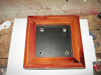
To create the display base for the vacuum tubes, start by attaching the 5" X 5" piece of black painted 1/4 inch plywood to the lid of the case. This is done by simply applying a bead of glue to the inside of the lid insert and adhering the plywood piece to the inside of the case lid. Allow the glue to dry.
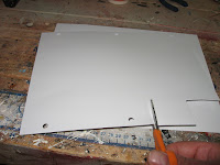
Next mark and drill the mounting locations for the vacuum tubes. To help in determining the location for the tubes, I found it useful to create a template of the tube bases in order to help in marking the location on the plywood base. To create the templates I created 4 small square pieces of paper that are roughly the size of the tube bases. With the 4 pieces of paper, punch a hole in the middle of them for the center insulator pin of the tubes (I create this center hole with a hole punch that you would use for a punch paper for a 3 ring binder) . With the center insulator of the tube in the hole of the paper square, trace the outline of the base on the paper and cut out the base outline with scissors.
Place the paper templates on the plywood top in the locations that you would like them positioned.
Once you have the templates in the position that you want, mark the location of the center holes of the templates on the plywood and remove the templates.
Using a drill press and a 1/4 inch drill bit, drill holes into the plywood top at the locations that you had just marked. Once the holes have been drilled, give the tubes a test fit on the case lid to ensure that they fit properly. Adjust if necessary.
As a last step, create the hole that will be used for the solar panel later on. To create the hole, mark the center of the plywood lid top and with the drill press and this time with a 1.5 inch bit, drill a hole in the center of the plywood top.
Step 11: Installing the LED's Into the Vacuum Tubes
With the case lid prepared, the next step is to install the LED's into the vacuum tubes.
The installation is fairly simple. Insert a 5mm flickering Red LED into the hole that we had previously drilled into the base of each of our vacuum tubes.
Once the LED's have been inserted into the tubes, secure the LED's to the vacuum tubes by applying a little bit of hot glue to the LED's.
Step 12: Installing the Solar Panel
To start installing the electronic components for the display, we first need to install the solar cell that will be used for charging the batteries that will be powering our LED's
The solar cell is installed on top be the case lid over the 1.5 inch hole that we just previously drilled.
Apply a bead of hot glue around the 1.5 inch hole on the top of the case lid..
Attach the solar cell to the top of the case, making sure that the solar cell is in the center of the case before the hot glue sets.
Step 13: Install the Vacuum Tubes Into the Base
With the solar cell installed, the next step is to attach the vacuum tubes to the case lid.
Start by bending the leads of the LED on each tube so that the leads hug the center pin of the vacuum tube. Make sure the the leads of the LED do not contact each other.
Next install the vacuum tubes to the top of the case lid by inserting the center pins of the tubes through the holes that we previously drilled into the lid top. Make sure the the LED leads for each tube is also placed through the hole in the case lid.
Once all the tubes have been installed, secure the tubes to the lid by applying a bit of hot glue to the center pin of each tube from underneath the case lid top. Be careful that you don't cover the LED leads in hot glue.
With the tubes installed, solder four 4 inch long insulated wires to each of the LED leads. To allow for easier installation to the power circuit later, solder a red wire to the positive lead of each LED and a black wire to the negative leads.
Step 14: Soldering the Solar Cell and Installing the Photocell
To prepare the solar cell for connection to the charging circuit, we start by connecting a diode and a lead wire to the solar cell.
Start by soldering a red wire to the positive terminal of the solder cell. Once that is complete, solder the cathode end of the 1N4006 diode to the negative terminal of the solar cell. The diode serve as a "check valve" for our LED circuit.
During the daytime, the solar cell acts as a power source, charging the batteries that power our LED's.
However, when it's dark out, and if left directly connected to the batteries, the solar cell will act as a draw on the batteries. The diode will prevent current from flowing into the solar cell from the batteries while allowing current to flow out of the solar cell to charge the batteries.
Once the wire and diode are connected to the solar cell. It might not be a bad idea to hook the solar cell up to a multi-meter as a quick quality check, You should get a decent amount (2-4.5 volts) of power coming from the solar cell, depending on your light source.
Once the solar cell is wired up, we need to install the photo cell that the circuit will use to determine when it's dark out (so to turn the LED's on in the vacuum tubes)
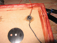
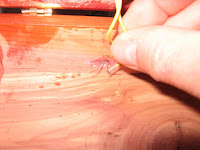
Start by marking a spot in the middle of the back of the case bottom. Once marked, drill a 1/4 inch hole at the marked spot. When the hole is drilled, insert the photocell so the the cell is flush to the outside back of the case bottom. Secure the photocell to the case with some hot glue.
Step 15: Attaching the Lid to the Base
We finally have come to the point where we can attach the top of the case to the bottom of the case.
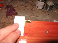
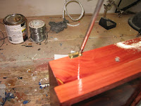
Start by taking two brass hinges. Place each hinge at the top of the the case bottom, set each hinge in one inch from each side of the case, making sure that the top half of each hinge is hanging over the top of the case bottom. Once the hinges are in position, mark the location of screw holes of the hinge on the case bottom.
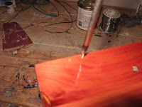
Remove the hinges, and using one of the screws that will be used to attach the hinges. create a pilot hole at each marked location by screwing in and then removing the screw for each marked location.
Once the pilot holes have been created, put the hinges back onto the case bottom and secure the hinges with screws, making use of the pilot holes that were just created.
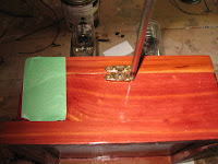
Next place the lid onto the top of the bottom of the case. Position the top half of the hinges on the lid and mark the location of the screw hole locations on the lid Using one of the screws that will be used to attach the hinges.
Create a pilot hole at each marked location by screwing in and then removing the screw for each marked location. Once the pilot holes have been created, put the hinges back onto the lid and secure the hinges with screws, making use of the pilot holes that were just created.
Now that the case and lid is attached at the back with hinges, finish by attaching a clasp to the front of the case. Position the clasp in the center of the case such the the top half of the clasp is on the lid of the case and the bottom half of the clasp is on the bottom of the case. Mark the location of the screw hole locations using one of the screws that will be used to attach the clasp. Create a pilot hole at each marked location by screwing in and then removing the screw for each marked location. Once the pilot holes have been created, attach the clasp on the case and secure the hinges with screws, making use of the pilot holes that were just created.
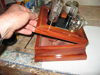
At this point you should now have a completed case the open and closes that can be secured closed with the clasp in the front.
Step 16: Building and Installing the Circuit
The circuit that the drives the LEDs and turns it on when it's dark out is actually very straightforward. (I got the original concept for this circuit from the Radio Society of Great Britain's excellent "Radio and Electronics Cookbook")
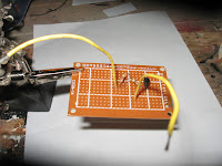
The brains of the operation for the circuit is the photo cell that acts a variable resistor (low resistance in the daytime, high resistance when it's dark out) that is used to trigger the transistor - which is then used as a switch to turn on the LED. The circuit is constructed using a small perforated board where the components can be mounted in the pre-drilled holes of the board. The components are connected to each other on the board using a "dead bug" method (where the component leads are soldered to each other).
A full circuit diagram can be found in the pictures above.
Start by mounting the 2N3904 transistor in the middle of the perf board. Solder the transistor in place.
Next, solder in the wires from the 4 LEDs that have been installed in the vacuum tubes. The LEDs need to be wired in parallel to each other. When soldering, make sure that the positive leads of the LEDs are connected to the Collector of the transistor.
Once that's done, mount the two 1 Kilo Ohm resistors to the board. Solder one lead from one of the resistors to the negative wires for the LEDs. With the second resistor, solder one lead to the Base of the transistor. Solder the unconnected leads for the 2 resistors together.
Finally, connect the photo cell to the perf board. First solder approximately 6 inches of hook up wire to each lead of the photocell that has been attached to the case. Solder one of the wires from the photo cell to the two 1 Kilo Ohm resistors and solder the other wire from the photo cell to the Emitter of the transistor.
To allow for connections to the batteries and the solar cell, cut 4 hook up wires (preferably 2 red and 2 black wires) that are a few inches in length. Solder one end of the 2 red wires to the LED and transistor Collector connection point.
Solder one end of the 2 black wires to the photo cell and transistor Emitter connection point.
Solder one of the black wires on the circuit board to the negative terminal of the solar cell. Likewise, solder one of the red wires on the circuit board to the positive terminal of the solar cell.
This should now give you a circuit that will turn on the LEDs when it gets dark. At this time give the circuit a quick test by hooking up the circuit to a battery source and turn off the lights - the LED should start flickering away! Likewise, with the lights on - the LED should go dark.
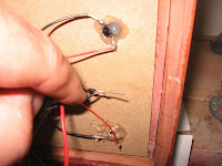
Once the circuit has been tested and is working, attach the circuit board to the lid of the case with a little bit of hot glue. While you have the hot glue gun warmed up, also take this time to tidying up the wires that are attached to the LEDs and secure them to the case lid too.
Step 17: Installing the Batteries and Finishing Touches
To wrap up the project, solder a 2 AA battery holder to the circuit board by soldering the red wire on the battery holder to the remaining red wire on the circuit board followed by soldering the black wire on the battery holder to the remaining black wire on the circuit board.
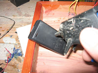
Apply a dab of hot glue to the back of the battery holder and attach the battery holder to the bottom of the wooden case.
Once the glue is dry, insert 2 rechargeable batteries to the battery holder, close the lid on the wooden case, secure the front clasp, and the project is complete
To provide a good initial charge, place the display case near a strong light source for a few hours.
After wards, if the display case is in close proximity to a good light source for an hour or 2 a day, the batteries should maintain a good charge,
I have this display in my office at work and I've found that it creates a great deal of attention from my co-workers, especially from my younger colleagues who ask what the strange "light bulbs" do.









































No comments:
Post a Comment