Now that I had all the pieces of the weather station now all put together and tweeting out the weather conditions inside of my home, it was pretty neat to see in action, but alas, not very useful. In order for the station to be truly useful, I really needed to have the sensors outside of the house.
The issue with anything electronic is that they don't really take exposure to the outside elements very well, however having them sealed inside a box won't provide any accurate readings. The solution is to have the sensors housed in some sort of container that will permit the entry of the outside air in order to get the most accurate temperature and humidity readings, but prevent nasty stuff like rain and snow from getting inside.
The solution for this type of situation is to build a Stevenson Screen, which is has been used by a lot of "professional" weather stations to house their instruments. I've made a Stevenson Screen before, however, I wanted to have a screen that was perhaps a little less noticeable, plus I now had a few more options at my disposal now than when I built my first screen.
This time around I wanted to build a screen that could sit fairly inconspicuously on my window sill. As a bit of a departure from the normal practice, I wanted to use a breadboard to mount the sensors versus soldering them to a perf board. The idea with this approach was to allow me to easily upgrade sensors anytime in the future if I wished. I realize that I may be asking for trouble since a breadboard isn't really meant for a long-term installation of this nature, but it would be interesting to see if it is a feasible option.
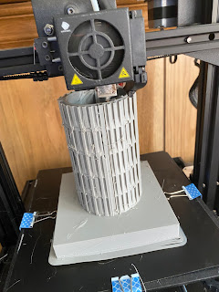
For construction, I determined that I would make this with the help of my 3D printer. Logging onto TinkerCAD, I did a quick search for Steven Screens and quickly came across a design by user "danielillu" that seemed to match what I was looking for a screen. However, I did need to make some alterations to the design before I could use it for my purposes.
For starters, I needed to make the screen a bit wider and longer in order to fit the breadboard inside the screen. Based on the size of my breadboard, I enlarged the screen so that it was 3 inches in diameter and about 7 inches long.
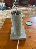
Since it was going to be sitting on a window sill, it needed to have a fairly large base for the screen to sit on. To make that work, I added a 4 X 4 square to the bottom of the screen that was about an inch thick.
Inside the bottom square, I also put in a 1/2 inch diameter hole that allowed access from the bottom of the base to the inside of the screen which I will use to feed wires to connect to the sensors inside the screen.
To get around this, I decided to use 2 cables for the sensor, the one cable, using 2 of its 4 wires, will be used to provide power to the sensors, The other cable will be used to read the sensor data.
I started by feeding the cables through the opening in the bottom of the screen until the cables were accessible through the top of the screen.
After that, it became a matter of hooking up the wires to the appropriate spots on the breadboard and on the Arduino, which I did by making sure that the correct colored wires on the phone cables plugged into the correct places on the breadboard and the Arduino.
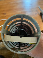
Once everything is wired up, I applied a little bit of electrical tape to the end of the breadboard in order to keep the cables in place and I carefully inserted the breadboard inside the Stevenson screen.
Once the sensors were installed, I then installed the cap on the top of the screen and I placed the screen on my outside window sill.
After plugging the Arduino into my PC, I was now recording the weather conditions outside - much better!


No comments:
Post a Comment