Last week I started building an enclosure for my 3018-PROVer router and I finished the week with the bottom or "tub" of the enclosure built.
This week I focussed on building a lid for the enclosure to keep the noise and dust down while the router was in operation.
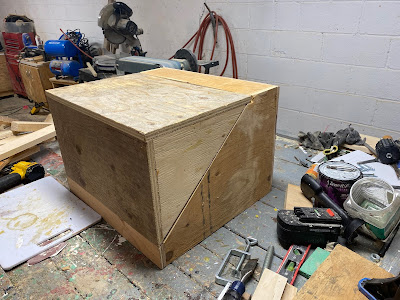
As I mentioned last week, I wanted to make the enclosure a bit like a clamshell with a shelf at the top to install the off-line controller box and a bit of a lip at the bottom to help keep the sawdust inside the enclosure.
Since the bottom of the enclosure, while still basically a rectangular shape, has a bit of an odd shape, so I needed to design a matched lid.
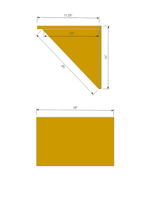
For the lid, I needed to construct something that had a top of 11.25 inches wide (16 inches minus the four inches for the top shelf for the offline controller) by 19 inches long and a front that was 10 inches wide (13 inches - 3 inches for the bottom lip of the enclosure) by 19 inches.
Since the sides of the bottom of the enclosure were cut at a 45-degree angle, the sides of the lid would likewise need to be cut at a similar angle.
I intended to use 3/4 inch plywood for the lid, so I discovered a bit of a flaw in my plans with the bottom since I noticed that the sides of the bottom did stick out a little bit of the top shelf would have prevented the lid from closing properly.
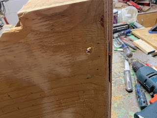
So before I build the lid, I first trimmed the excess wood from the sides of the bottom using a chisel until I had it flush with the bottom of the shelf
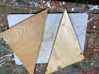
Factoring that 3/4 inch lip at the top of the enclosure, I figured that I needed triangles cut to 11" X 13" X 15" for the sides
With that little issue corrected, I sketched out a design for the lid.
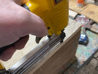
Satisfied that things were nice and square, I then attached the front to the top of the lid with some glue and brad nails.
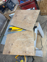
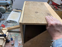
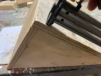
After that, I cut 2 triangles out of plywood at the size that I had determined and attached them to the top and front of the lid with glue and nails.
This effectively completed the construction of the lid, and a quick test fit confirmed that the lid was able to form a fairly tight seal with the base of the enclosure
Before I started the final assembly, I did want to add a couple of refinements to the enclosure.
The first thing that I wanted to do was add a small viewing port to the top of the enclosure so that I could monitor my work without having to open the lid.
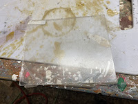
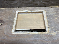
From a previous project, I had a 5" X 6" piece of plexiglass that thought would be a perfect window to the world inside the enclosure. My plan was to cut a slightly undersized opening into the lid and glue the plexiglass inside the lid along the overlapping edges.
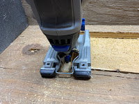
I started by drawing a 4.75" X 5.75 rectangle (which would give me a 1/8 inch border to attach the plexiglass to the lid) and cut the opening out with a rotary tool.
Flipping the lid over I then routed a channel along the edge of the opening to create an attachment point for the plexiglass.
With the viewing port made, the next thing I wanted to do was to add some sort of ventilation for the router's motor controller, since I did notice that it did get a bit warm when the router was running.
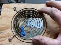
To do this I had a fairly large fan that I salvaged from an old computer, which I plan to use to blow air onto the controller.
To install the fan I needed an opening in the back of the enclosure roughly in the spot that the motor controller would be when the router is installed in the enclosure.
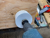
To make the opening, I selected a hole saw that was roughly the size of the fan and I cut a hole into the back of the enclosure at the place where the motor controller will be,
While I was at the back of the enclosure, I also cut a 2-inch wide slot near the top to allow the ribbon cable for the offline controller to pass through with my rotary tool.
And to finish off, I drilled a 3/8 inch hole in the right side of the enclosure bottom of the power cable for the router.
With that, the next step is to finish everything up and install the router.









No comments:
Post a Comment