Last week I tried out a project from an old issue of Popular Mechanics where you could make a voltmeter for your car.
Wiring up the voltmeter was actually a pretty easy project to tackle and I was able to get it up and running with a couple of hours of soldering.
As s temporary measure, I put the meter in an old plastic food container while I was out driving around.
While functional, it certainly wasn't very attractive to look at.
As I may have mentioned before, I recently got a 3D printer and I have been spending a bit of time getting acquainted with it by printing out a few "canned" 3D models that I had found online. While I did enjoy printing out some of the things that I had found, I really wanted to make my own custom parts, which is the main reason why I wanted the printer in the first place.
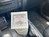
As a first project that I can make "on my own" with my printer, I figured building a custom case for my meter would be a nice and simple project to try out.The requirements for this case was that it needed to be designed so that it could be mounted someplace that would be relatively secured, yet be easy to read the meter while driving and be fairly easy to remove if I wanted to use it on another vehicle. Doing a scan of what options I had for mounting the meter in my truck (without drilling holes in my dashboard), I settled on building something that would fit into one of my vehicle's cupholders.
While it would mean that I would lose a cupholder, we all need to make sacrifices sometimes.
To design the cabinet, I needed to use some sort of modeling tool to create the 3D model that I wanted to print out. There are quite a few tools that I could have used for this but settled on using Tinkercad to build my model because I found it to be a very easy tool to learn and it seemed to have a very good online community in case I needed any help.
After some sketching on Tinkercad, I eventually came up with a model that I felt would work.
At its heart, it's a very simple design that is comprised of 2 main parts, a box with an opening that is big enough to fit the meter inside it (the opening and the overall size of the box are based on the measurements of the meter), and a cylinder that had a big enough diameter to fit into a cupholder. The cylinder also had a cavity inside it that allowed the containment of the meter circuitry.
There was also a small hole cut into the back of the cylinder and box to allow wiring access between the cylinder and the box and to allow access for the power cable.
The box sits on top of the cylinder at a 30-degree angle with the meter opening facing up.
The full model can be seen in more detail here
With the model sorted out, I next had to create the GCODE for the printer to understand what I wanted.
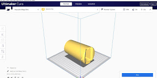
To do this I needed to download my model as a GLTF file and load it into a slicing tool (Ultimaker Cura in my case).
While I could easily print the whole case as a complete unit, I decided that splitting the project into 2 pieces (the box and the cylinder) on Cura would probably make things easier.
As part of my design, I made the cylinder a little larger than the box, which creates a little socket for the box to sit in. The idea will be to make the box attach to the socket by friction fit, or at minimum be secured in place with glue,
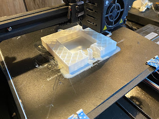
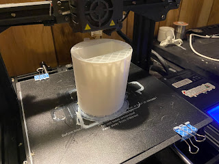
After generating the GCODE on Cura I then loaded the programs up on my 3D printer and started making my parts
While it's pretty neat that we live in an age where we can make things that can magically show up in real life directly from your computer screen, it still takes a few hours for the printer to work its magic.
While I was waiting for my parts to appear, I focused on the meter. The original Popular Mechanics project was kind enough to provide a dial that I could attach to the meter, however, it didn't accurately match the readings that my meter was providing.
For the voltmeter to be of any lasting value to me, I really needed to have the dial show accurate readings.
I set about to create my own dial. Searching online I found a few sites that provided blank panel meter templates that you can modify to reflect whatever value you want to show.
By this time, the parts were printed and things were ready for assembly.
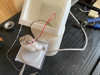
Assembly was started by feeding the meter wires through the hole in the back of the cylinder and tucking the circuit for the meter into the cavity of the cylinder.
Next, I fed the meter wires through the hole in the box for the meter and attached the box to the cylinder by seating it into the slot that was cut into the cylinder until it clicked into place.
Finally, it was time to install the meter. I attached the wires to the posts on the meter and I slid the meter into the cavity of the meter box. I had measured the opening just a shade smaller than the dimensions of the meter, so the meter was held in place by a friction fit.






No comments:
Post a Comment