I've always been a bit fascinated by the weather. If you take a look at some of my past posts on this site, you will find the odd little project that either entails tracking the weather conditions or using something weather-related (usually solar-powered) to drive some sort of device that I've dreamed up.
As a kid, my grandmother had a few whirligigs in her backyard that performed some sort of activity whenever the wind blew. More of them performed some sort of crude animatronic action, like making a lumberjack saw a log or a donkey kicking a bucket over, I was fascinated by the concept that some invisible force was making all this happen.
In subsequent years, I did some experimenting by hooking up a fan blade to a stepper motor and a LED and watching the wind create the power to light up the LED, but I couldn't really something really tangible to apply it to.
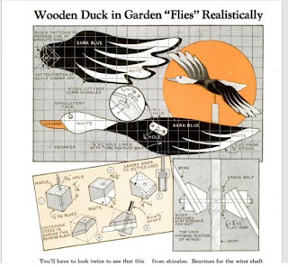
I hadn't really thought too much of it for a while until I recently found a plan for a pretty simple-looking duck whirligig in an issue of Popular Mechanics that was published back in 1940.
With the arrival of spring, I start planning what sort of offerings I should put on my front lawn for passers-by to stop and purchase. As a habit, I usually try and put something new out each year in order to keep things fresh. When I spied the duck in the magazine, I figured that it may be a worthy addition for my wares on the front lawn.
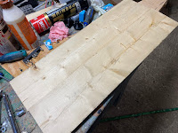
Using some pine planks that I had on hand, I set about to build the whirligig just as it was specified in the article.
The end result did look pretty good, but I found that it took a great deal of wind to make the duck fly. '
Ideally, the wings of the duck need to turn with the slightest of breezes. The obvious solution is to double up the wings, typically with the wings attached to the sides of the duck, with 2 wings on each side.
While easy enough to do, I really did want to try something a little different.
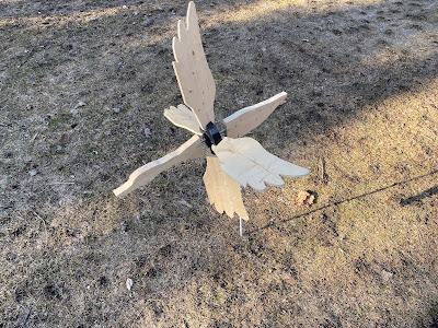
After some quick doodling, I came up with a plan to create a whirligig that had a more traditional whirligig design, which is typically a 4 bladed propeller that is placed perpendicular to the body of the whirligig. however, instead of having the blades installed at one end of the body, I would instead install the blades at the midpoint of the whirligig's body. With the blades shaped like wings, it would still give the duck the appearance of flight when the blades are spinning.
By utilizing the template that was provided in the magazine article, I felt that I would still be able to maintain the look of the original plan from 1940.
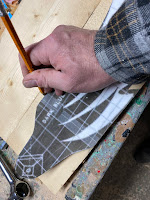
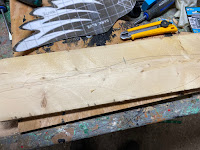
I started the build by cutting out two 24 inches long 1/4 inch thick pine planks and traced out four-wing outlines onto the planks. After that, I cut the wings out with the scroll saw.
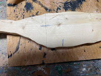
Next, I took a 1/2 inch thick, 24 inches long length of pine plank and I traced out the outline of the duck's body on it. After that, I also cut it out with the scroll saw,
To install the blades. I needed to cut the duck's body in half at the point where the wings would have been attached. Using the template that I had, I made a mark where the template indicated where the wings would have been attached and I then cut the body into 2 halves at that mark using a miter saw.
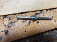
To attach the blades to the body of the duck, I settled on having an 8-inch long length of 5/16 threaded rod that will be inserted into each end of the duck's body. In the middle of the rod, I plan to install a small (8mm x 22mm x 7mm) ball bearing which will be secured in place with two 5/32 nuts and lock washers.
To mount the rod into the duck's body, I drilled a 1/4 inch at the ends of each half of the body to a depth of about 3 inches. This is a slightly undersized hole for the threaded rod, however, the idea will be to have the rod screw into the holes, creating a nice tight connection.
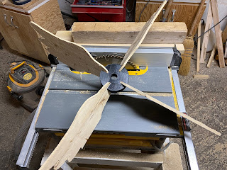
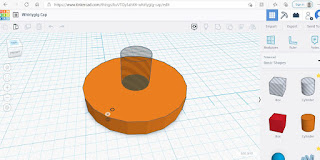
To attach the blades to the bearing, I wanted to create a hub that would have an inner diameter of 22mm to fit the bearing and four 1/4 inch wide slots on the outer diameter for the wings. To make sure that the wings properly caught the wind, the slots would be tilted at a 22-degree angle.
I can easily create the hub out of wood using a 3-inch hole saw and a 22mm drill bit in the center, and cutting the slots with my table saw with the blade set at 22 degrees. However since I didn't really want to deal with trying to cut angles on a small piece of wood with my saw,
I settled on my creating the hub with my 3D printer After printing out the hub I then attached the wings by siding them into the slots. The wings easily held in place by friction, but to secure them further, I also used a touch of exterior wood glue.
With the caps installed the blades were attached to the duck's body by screwing the rods into the holes that I had drilled into the duck's body earlier. I found it a bit easier to screw the threads in with the help of pliers.
After the body was attached I drilled a hole in the bottom of the back half of the duck's body about 2 inches back from the wings for mounting the duck on a pole
The duck was ready for a test flight.
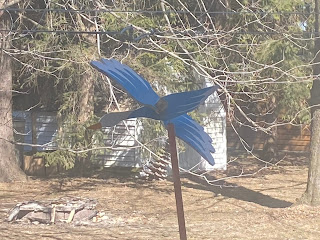
I found the wings now turned easily with a very slight breeze. While I did have some concern about the pole mount being a bit further back than the duck's center of gravity, it did seem to sit and pivot on the pole without too much trouble.
While I haven't had a chance to see how it would fare in a wind storm yet, I am confident enough with the design of my prototype that my next step will be to properly paint the duck and install it in a more permanent place.
While I am still not convinced yet to make a pile of these for sale on my front lawn since I am not sure how durable 3D printed parts are for this type of application, but I will be making a few of these for my backyard to test out over the summer. If they survive, there will be a flock out them in front of my house next year.
But for now, time to do some painting.










No comments:
Post a Comment