While cars today are technological marvels that seem to have so many smarts built into them that they seem to almost drive themselves - I can distinctly remember when I first got my 2017 Honda Ridgeline out on a road trip and being a little freaked out at first when I would feel the steering wheel turn by itself when I was going into a curve on the road.
Unfortunately, as the cars get smarter, the less they seem to want to tell the driver how the car is doing mechanically. Many years ago a lot of vehicles had gauges on the dashboard that told the driver such pertinent details as the old pressure, coolant temperature, and battery/alternator voltage. Except for some pickup trucks, most cars these days only give you the engine temperature as a gauge, relying on warning lights when the oil pressure and voltage get too low. The issue is that by the time you see a warning light, is usually too late and you are stuck by the side of the road.
With gauges, you had the opportunity to spot trouble before it had a chance to leave you stranded. The movement of a needle on a dial off of its normal spot would always give you a clue that things were starting to go bad under the hood.
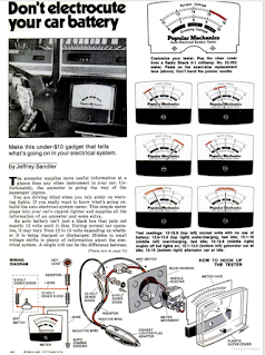
As I mentioned in one of my previous posts, I have been browsing through the back issues of Popular Mechanics magazine. The other day I was leafing through the October 1977 issue when I came across an article on building a testing tool that measured the health of your car's charging system.
The tester used your car's cigarette lighter socket as a power source and was able to determine the health of your car's electrical system by measuring the battery during cranking conditions and the health of your alternator while the engine was running.
This was a very simple project that only required a cheap amp meter and a few electronic components.
Intrigued by the simplicity of the project and the idea of having a voltage gauge for my Ridgeline, I set about constructing one during a rather stormy evening.
At its heart, the project comprises a resistor, a 12 Volt Zener diode, and a 6 volt Zener diode which are connected to a 1 milliamp meter. In the article, the parts were sourced from Radio Shack and included the Radio Shack part numbers to make it easy for you to run down to your local Radio Shack and grab the parts.
Of course, Radio Shack is no longer with us (which is a bit of a shame, since I really looked forward to thumbing through the new Radio Shack catalog every fall when I was a kid). So while I could find the parts online from the provided parts numbers, the search results invariably turned up eBay "vintage parts" listings with "antique store" prices attached.
However I was able to determine the type of diode I needed and with a quick stop at Amazon, was able to source parts pretty easily.
To make the meter, I needed the following parts:
- One 1N4742A Zener Diode 12V (Got a pack of 20 on Amazon for $7)
- One 1N5340BR Zener Diode 6V (20 pack on Amazon for $7.50)
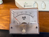
- One 0-1 milliamp meter ($12 on Amazon)
- One 3.9K Ohm resistor ( $8 on Amazon got me a bag of 100 of those)
- One 12v Male LED Car Cigarette Lighter Power Socket Plug Connector (about $5)
- A length of 2 wire hook-up wire
To start the build, I first took a length of hook up wire and stripped the insulation off of both ends, exposing the two wires
Next, I took apart the power plug and soldered the positive (red) wire to the center terminal of the plug, and soldered the negative (black) wire to one of the outside clips.
After that, the plug was reassembled,
The other end of the wire will contain the circuitry that will in turn be connected to the meter.
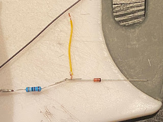
When looking at the plans in the article, I noticed that the resistors and diodes were soldered together in a chain, a bit different than my usual method of having everything connected on a small square of perf board. However, I did see that the method that they illustrated did make for a much smaller footprint, which very useful if I wanted to install the meter in a compact space.
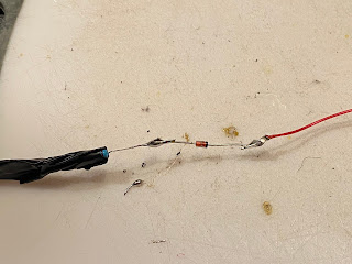
To build the circuit, I first soldered one end of the 3.9K Ohm resistor to the red positive wire,
After that I took the 12 Volt Diode and soldered it to the other end of the resistor, making sure to solder the end of the diode that did not have the stripe marking. At the same time, I also soldered in a small jumper wire to make connecting the 6-volt diode easier.
After that I soldered in the 6-volt diode to the jumper wire, again making sure that the end of the diode that did not have the stripe was connected to the wire and soldered the other end of the 6-volt diode to the other end of the 12-volt diode.
I finished off by soldering a length of red wire to the "striped" end of both diodes.
I connected the meter to the red and black wires and I was ready to test it out.
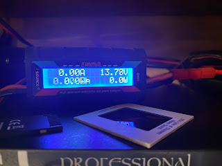
I am lucky to have a power supply that had a 12 Volt power socket and an inline digital meter that gave a pretty accurate voltage reading.
When I first plugged in the tester to the power supply, the meter's needle got immediately pinned to the maximum setting.
Basically, there was too much juice going to the meter.
The only logical conclusion was that the meter that I had obviously did not have the same specs as the original Radio Shack meter that the article called for. The only real fix for this was to increase the resistance until the meter read something more reasonable.
On average, when a car is running, the alternator is putting out around 14 volts, or in the case of my power supply, around 13.8 volts. Based on that assumption, I wanted to have the needle sit in the middle of the dial when it is at that voltage.
To figure this out, I un-soldered the resistor from the red wire and started to put some 3.9K Ohm resistors in series on a breadboard until I had the needle where I wanted it.
Based on the resistors I used, I determined that I actually needed a 26K Ohm resistor for things to work properly. (or in my case, 22K Ohm and a 3,9K Ohm resistor, since I didn't have a 26K Ohm resistor on hand).
With that revelation, I replaced the resistor and the meter was now behaving as expected.
With the circuit sorted, I then looked to change the meter dial so that the readings would make a bit more sense.
The Popular Mechanics article was kind enough to provide a full-size dial template which made it a fairly simple matter of just printing it out on my printer.
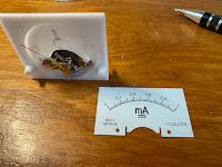
Replacing the dial on an analog meter is usually pretty simple. The cover for the meter is usually attached to the meter's body with two small machine screws and the cover simply lifts off the meter once the screws are removed.
The next part can get a bit tricky. To remove and replace the dial from the meter will need to be done carefully in order to not damage the needle, however, it too is a fairly easy matter of removing 2 screws and removing the meter.
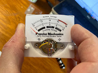
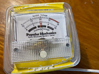
To install the new dial, I printed out the dial that was provided in the magazine article on a sheet of sticker paper and trimmed it down to the same size as the original dial.
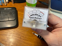
After that, I carefully stuck the new dial onto the meter and replaced the cover.
Giving the dial another test with my power supply I noticed that the meter wasn't quite measuring what was indicated on the display for the power supply. This was corrected by giving the meter's adjustment screw a small turn with a screwdriver until the meter showed the correct voltage.
As I was doing the adjustments, I did notice something.
I was a bit curious about the purpose of the 6-volt diode. It finally hit me when I took a closer look at the markings on the new meter dial. Along the bottom of the dial were markings for cranking voltage between 6 and 10 volts, This is all well and good if the 12-volt power socket is always powered even when the vehicle is shut off.
However most modern cars these days do not have the 12-volt power socket powered on unless the car is running, meaning that there is really no way of testing the cranking voltage since there will be no power to the meter while the cart is being started
With this revelation, I realized that the 6-volt diode was pretty much useless, so I removed it from the circuit with no impact to the meter's function
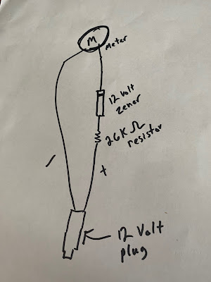 |
| Revised circuit |
Removing the extra diode made for a much more compact circuit.
To finish up the circuit build I then wrapped up everything with a bit of electrical tape.
With all the electrical parts all buttoned up, the final step was to house the meter in some sort of case for use in the car.
I do have a more elegant solution in mind, with the help of my 3D printer, but for now, I used an old food container by cutting an opening on one side of the container to allow for the mounting of the meter with the electronic components stored inside.
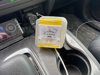
The final step was to take everything out to the car and plug it in.
I am quite impressed with how sensitive the meter is to voltage fluctuations while I'm driving around, I can see when the alternator is charging the battery when the needle spikes up in voltage whenever it kicks in. Likewise, I can see an equal decrease when the battery has been charged.
The only thing that I have noticed however is that the needle isn't really linear in its measurements.
While it's calibrated to have 14 volts at its center point, when the voltage is at 12 volts, the needle actually reads at a higher voltage. Again, I chalk it up to using a different meter than what was specified in the magazine article, so I will need to look into creating my own meter dial that indicates the voltages more accurately.
However considering using only a few cheap parts, I now have an intimate view of my car's electrical system's health, certainly very cheap insurance from avoiding a breakdown on the road.















No comments:
Post a Comment