In my last post, I designed and built a cabinet for my Raspberry Pi radio scanner. Now it is time to wrap this project up and install all the electronic bits into the cabinet.
As a first step, I gathered up all the bits of the cabinet, Raspberry Pi, and other components and laid them out on top of my work table.
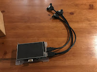
The other components included the SDR dongle, the USB sound card but also included 3 short USB extension cables that I had picked up from Amazon for a few dollars.
There are a few reasons for those extension cables. The one cable is to be used as an external USB connection for the Raspberry Pi, while the other 2 will be used to attach the SDR and sound card to the Pi because I was finding that the dongle and sound card were crowding out the USB ports on the Pi, causing a bit more strain than I would like on the USB ports.
With all my parts gathered together, the next step was to install the Pi into the cabinet.
My Raspberry Pi 4 came with a small LED screen that was attached to the PI with a clear Plexiglas frame. This frame held the screen against the Pi and everything was held together as a complete unit. This frame also has a front faceplate that extended out in front of the screen by a few millimeters.
This faceplate would be the perfect way to attach the screen and Pi to the cabinet. To do this I first removed the faceplate from the screen by removing a few screws.
After that, I placed the faceplate inside the cabinet and centered it over the cabinet's front opening.
Once I was happy with the position, I secured the faceplate to the cabinet by running a bead of hot glue along the outside edge of the faceplate.
With the faceplate installed in the cabinet, the next major step is to install the Raspberry Pi itself.
Since the sides of the cabinet are fairly close to the Pi when it's installed, in order to make the installation easier, I needed to plug in all the cables into the Pi before it goes in.
I started by plugging in the power cable by routing the cable through the back panel of the cabinet and plugging it into the Pi.
Next, I plugged in the 3 USB extension cables,
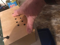
Also before installing the Pi, I installed the speaker into the cabinet by placing the speaker behind the grill that has been cut into the case and attaching it to the cabinet with some hot glue.
To install the Raspberry Pi I just reseated it in the faceplate in the cabinet and reattached it with the screws that I had removed earlier.
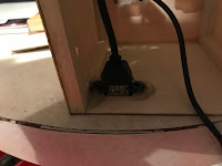
With the Pi in place, I then took one of the USB extension cables and placed it over the side opening of the cabinet and hot glued it in place.
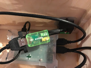
Next, I plugged in the SDR dongle and the USB sound card into the other 2 USB cables.
Tucking the sound card into the cabinet I plugged in the headphone jack on the card to the speaker.
I next needed to sort out my antenna situation.
The antenna that came with my dongle has been optimized for the DTV frequencies in Europe, which is typically in the 800Mhz range. Since the stock antenna is optimized for that frequency range, it is a pretty stubby affair that probably would not work very well at the frequency of my local fire department, which is in the 158 Mhz range,
In order to have my scanner working at its best, I needed to somehow adjust the length of my antenna to match the harmonic length of the frequency that I want to receive.
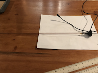
Luckily the antenna that came with my dongle was easily removed by unscrewing it from its base. Even luckier I found that the antenna's base was about the right size of the spacer stand-offs that you typically find attached to old computer peripheral cards that were used to secure I/O cables to the card was the right size to screw on the base.
.I also had on hand some copper welding rods that were a couple of feet long.
First I needed to figure out what I needed the length of my antenna needs to be - which I will be making out of the welding rod.
To do this I needed to calculate the quarter wavelength of the frequency that I wanted in order to keep the antenna as small as possible. While the formula for this pretty straightforward, there are a lot of online calculators that can do this a lot quicker.
So I called up one of those calculators, plugged in 158 Mhz, and got the length I needed - 1.557 feet
The last step was to solder the rod to the end of the standoff and screwing the new antenna onto the base.
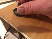
Next, I fed the connecting wire for the antenna through the top opening of the cabinet and I glued the antenna's base to the top of the cabinet.
In order to reduce the possibilities of interference from any possible spurious signals. I wrapped up the excess antenna cable into a torrid and plugged the antenna connector into the SDR dongle.
This completed the installation of the components into the cabinet. The final step was to attach the back panel of the cabinet. Since I wanted to have the potential of removing the back panel for any later upgrades, I applied a small dab of hot glue at each corner of the cabinet back and attached the cabinet in place.
If I wished to get inside the cabinet again, all I needed to do was to slide a small blade (like a utility knife) along the four corners of the cabinet's back.
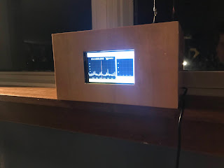
The final step was to plug it in, set the scanner to the frequency I needed, and start listening to the action.











No comments:
Post a Comment