Now that I have my Raspberry Pi pulling in the local radio stations and playing some tunes, I really needed to find a way to have the music play at a volume that an average human can hear.
The simplest way to do this is to plug some sort of amplifier into the phone jack of the Raspberry Pi and have it put the sound out to an external speaker.
There are a lot of pre-built circuits out there that you can simply buy and plugin. While that can be a very easy solution to the problem, it would be a strangely unsatisfying thing to do from my point of view. I have never really built an amplifier before. since I am just looking to have something that can broadcast public safety transmissions and I don't really care if it was high fidelity quality sound I figured that this would be a perfect time to learn how to build one.
Doing a quick look around the internet, I did find a lot of amplifier circuits of varying amounts of complexity, but I eventually settled on a circuit that was based on the LM386 chip set - Which I actually had a few on hand in my parts box.
The LM386 is an integrated circuit containing a low voltage audio power amplifier and is commonly found in a lot of battery-powered applications like radios. The chip can output 0.25 to 1 watt of power, which is plenty of power to hear things and more importantly, can run quite happily on the same 5 volts as the Raspberry Pi.
After looking at all the options, I settled on a design that only required 3 components to work - all of which I also had on hand:
- The LM386 chip
- A 1000uf electrolytic capacitor
- A 1.5 Kilo Ohm resistor
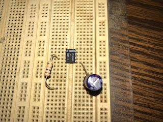
To build the prototype, I first installed the LM386 in the middle of a breadboard.
Next, I connected the V Out pin of the LM386 to the positive lead of the 1000uf capacitor. The negative lead of the capacitor was inserted into an empty row on the breadboard.
Next, I placed one end of the 1.5 Kilo Ohm resistor to the + input pin on the chip and inserted the other end of the resister to an empty row on the breadboard.
Next, I did up the wiring of the project as outlined on my sketch, This included connecting one lead of a speaker to the negative terminal of the 1000uf capacitor and the other lead of the speaker to the Ground pin on the LM386.
The other end of the 1.5 Kilo Ohm resistor was connected to the center pin of a 3.5 mm phone plug and another wire was connected between the outside shield of the plug and the - input pin of the LM386. The - input pin was then connected to the Ground pin on the LM386 with a small jumper wire.
Finally, I did up all the power connections by connecting a wire to the Vs pin on the IC which will be connected to the positive terminal of my power source and the Ground pin of the IC will be wired to the negative power terminal
Will all the wiring complete, it was time to plug in the power and phone plug into the Raspberry Pi and give it a try
It worked quite well!
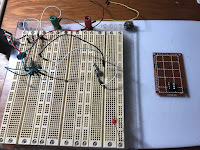
Since I am satisfied that the circuit will do what I wanted it to do, the next step was to transfer the circuit over to a proper circuit board.
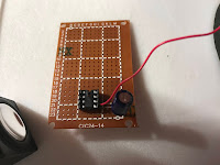
To build the circuit I took a small perf board and soldered in an 8 pin chip mount on one end of the board. The reason for the chip mount is to provide a "safe space" for the LM386 to avoid having to solder the leads of the chip. Directly soldering IC chips has a rise of wrecking the chip due to the high heat levels that solder entails. In this case, the mount takes the heat from the solder and the LM386 just simply clicks into the mount afterward.
I also mounted the chip on one end of the board to allow for any additional electronic bits that I might want later to enhance the amplifier.
With the mount in place, I basically just replicated the circuit that I had on my breadboard.
Since I already knew that the components I had on the breadboard working, I figured that the easiest approach was to move the components from the breadboard and directly solder them in the corresponding location on the perf board.
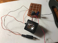
Once the components were soldered in place, again using the breadboard as a guide, I then soldered in the speaker and the various bits of wire needed to connect everything together so that it matched what I had sketched out on my circuit diagram.
It still worked well, but I did notice that there was a slight buzzing coming from the speakers when the amplifier was not plugged into the Raspberry Pi. From what I can tell, the buzzing was coming from the power supply that I was using to power the amplifier.
To solve that I placed a 60 pf ceramic capacitor between the positive and negative power terminals of the amplifier, or basically I had to make a small change to my circuit so it looked like this:
I now have a fully working amplifier for my radio receiver. The only issue that I have now is that it now seems to me that using a Pi 4 is a bit overkill for this type of application.
I should look for something a bit more appropriate.


No comments:
Post a Comment