The other night I heard a great deal of fuss emanating from the kitchen.
Poking my head around the corner, I noticed my spouse was in the midst of mixing a batch of chocolate chip cookies (yum), however, after 10 years of faithful service, the electric mixer that she was using had decided at that moment to cease functioning.
The mixer was still making the appropriate noises that you would expect, but the beaters were definitely not beating anymore.
Initial diagnosis - stripped gears
After finishing mixing the cookie dough the old fashion way and doing some quality control testing of the resulting cookies, I decided it was time to take a look at the mixer and find out what really killed it.
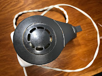
On initial inspection, the mixer is really no different than any other kitchen appliance that you see lurking in your kitchen cupboard.
It is made from a tough plastic material, but it did have one thing that was a definite bonus - it was all being held together with Phillips screws - a real rarity in a time where manufactures are designing products that prevent people from opening them up and heaven forbid, trying to fix them.
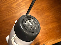
Taking out my Philips screwdriver, I proceeded to remove all the screws that I could find.
I then started the disassembly of the mixer by removing the back cap which basically appeared to serve as some sort of cooling vent.
The cap easily lifted off the mixer, exposing what appeared to be the back end of an electric motor.
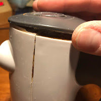
The end cap also acted as a clamp that held the bulk of the mixer's housing together.
With it now removed, the housing was easily split apart with a little bit of help from a slotted screwdriver.
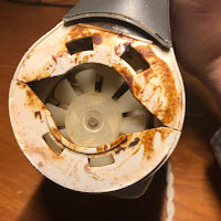
As I was removing the housing, I was finding a lot of dirt - most likely very old flour - crusting up the inside, which may be a clue to what caused the mixer's demise.
Once the cover was removed, the innards of the mixer were exposed.
At first look, the makeup of the mixer, not surprisingly, was pretty simple. The mixer was made up primarily of an electric motor, a rheostat to control the speed of the beaters which was done by changing the speed of the motor and some gears connecting the motor to the beaters.
As I mentioned earlier, I was finding a fair bit of crusty stuff inside the mixer. The bulk of the crust was congregating around a small fan that was connected to the motor's driveshaft. The purpose of the fan would appear to be to suck in air to cool the motor.
I suspect that I will just keep finding more of that stuff as I keep digging.
Behind the fan was a plastic housing that appeared to contain the gearbox that drove the beaters.
This is where I suspect I will find the root cause of the mixer's failure.
On top of the housing was a 2 prong piece of plastic that fits into 2 holes going into the gearbox housing. The piece of plastic was normally held out of the holes with 2 springs. The purpose of this set up was to act as a plunger which would eject the beaters out of the mixer when the plunger was pushed down.
Removing the plunger was just a simple matter of lifting it out of the holes.
Along with the plunger, there was also what looked to be a fairly simple rheostat switch which was mounted in the handle of the mixer.
The switch was wired directly to the motor, which was rather interesting since I would have almost expected some sort of electronic speed controller to manage the speed of the mixer.
Instead, it appeared that the motor speed was set by turning on certain parts of the motor coil with the switch. This certainly made it a very simple design which meant that there was little potential for failure, at least with the control of the motor was concerned
I was also surprised at the amount of flour that was caked around the switch.
Flour can be flammable and with the potential of sparks from the switch I was surprised that there wasn't an inherent fire risk with this design.
After examining some of the external features, it was time to dive into the gearbox. The plastic cover for the gearbox was secured in place with a couple of Phillips screws.
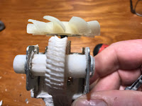
Removing the cover showed what looked like a metal worm gear on the shaft of the motor driving two plastic gears that in turn drove the mixer's beaters.
Additional inspection uncovered that the whole gear assembly and motor were also secured to the bottom of the mixer case with more Phillips screws.
When these final set of screws were removed, the gearbox and motor came out as a whole unit.
With the gears out of the housing, I could see right away what caused the mixer's failure.
The plastic gears were effectively stripped.
Continuing on with the autopsy, I started to separate the gearbox from the electric motor.
The gearbox was held in place within a metal frame that was also held together with Phillips screws.
The screws were tucked in behind the fan. Some gentle prying with a slotted screwdriver removed the fan from the electric motor's driveshaft.
With the screws now accessible, some quick work with a screwdriver disassembled the gearbox and freed up the motor.
Finally, I found that the motor itself was held together with a couple of screws which allowed me to reduce the whole mixer to its component parts.
When looking at the inside of the motor, particularly at the wiring going to the switch, my assumption was confirmed - the speed of the mixer was controlled by what section of the motor coil was activated.
A very simple and effective design choice.
So, in the end what was salvageable?
For my purposes, not a whole lot.
While the motor might have been useful, I didn't really have a need for a 120 V AC motor, so in the end I was only able to salvage the small fan and the rheostat switch.
It was a pretty useful exercise though.
I little surprised to see such robust engineering in some parts of the mixer, but absolute cheapness in other parts, which was what ultimately doomed the mixer.
If they had used metal gears instead of a plastic one, I would have probably bet money that the mixer would have lasted for decades, and really, it would have not cost much more to do that.
Oh well...









No comments:
Post a Comment