After a few months of puttering away on the junkyard entertainment system, the end is finally in sight.
With the completion of the display and DVD units of the system, the only thing left to do to complete the system was to give it a voice.
As you may recall in a previous post, I constructed and tested an infrared transmitter and receiver system that would allow the entertainment system to transmit sound wirelessly. Now that we have installed the transmitter part of this arrangement into the DVD player, we needed to give the receiver the same treatment.
Therefore the focus of this post will be on building a wireless speaker. Even though these particular speakers will be for our entertainment system, you can build these for almost any situation where you would like to have wireless sound.
Construction of the speaker itself is fairly straight forward since it really comprises of 3 main components:
- A Speaker
- A cabinet for the speaker
- The infrared receiver to drive the speaker.
Almost any speaker will work. In my case, I picked up some very inexpensive car speakers that came with their own speaker grill at my local surplus store.
Likewise, the speaker cabinet in itself is fairly easy to build.
To build the cabinet, I based the dimensions around the speaker grill and the depth of the speaker itself. Based on that information I determined that a finished speaker cabinet of 6 inches by 6 inches with a depth of 5 inches would work the best.
Armed with that information, I cut out four pieces of 1/2 inch birch 6 inches wide but a little longer than 6 inches in order to allow for some trimming for length later.
The next step in the process was to prepare the sides of the cabinet. More specifically I wanted to add a 1/2 inch groove along each edge of the sides in order allow for the speaker grill and back of the cabinet to seamlessly and snugly fitted into the sides when everything was assembled.
To create the grooves, I installed a 1/2 inch straight bit into a router and set the router's cutting depth to 1/4 inch.
When the router was set up, I took the 1/2 inch birch boards and just ran the two long edges of the boards through the router such that I had a 1/2 inch wide and 1/4 inch deep groove along each long side of the boards. While doing that also I made sure that the grooves are on the same side of the board.
Once the grooves were in place I then switched the router over to a round over bit and rounded over one of the edges opposite from the side that we put the groove on. This edge will act as the front of the cabinet go forward.
With the edges prepared I then cut a 45-degree angle off of one end of the boards, making sure that the "long" part of the 45-degree angle was on the side of the board that does not have the groove.
Using the speaker grill as a template I then cut the boards to size by cutting a 45-degree angle at the other end of the boards, again making sure that the long part of that 45-degree angle was on the side that did not have a groove.
Using the speaker grill as a template I then cut the boards to size by cutting a 45-degree angle at the other end of the boards, again making sure that the long part of that 45-degree angle was on the side that did not have a groove.
Taking one of the boards, I then marked and drilled a 5 mm hole 1.5 inches in from the back and bottom of the board. The purpose of the hole will allow the sensor from the receiver access to the outside world.
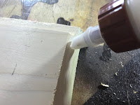
Now that all the cabinet pieces have been cut out, the body of the cabinet can be assembled. I started by applying glue to a 45-degree edge of two of the boards. I then joined the two other boards to the glued boards so that I had 2 half squares.
When assembling the boards, I also made sure that the sides that had the rounded over edges were both on the same side.
I then clamped the joined pieces together with corner clamps and allowed the glue to dry.
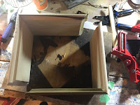
When the glue had dried, I removed the clamps and applied glue to the remaining 45-degree edges. I then joined the 2 half squares together and clamped them with the corner clamps until the glue had dried.
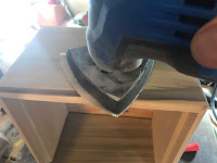
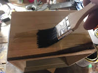
With the body of the cabinet built, this was a good time to give things a good sanding and a couple of coats of varnish.
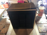
Once the varnish had dried, the speaker was installed.
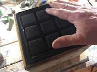
Installation was simply a matter of applying some hot glue along the back edge of the speaker grill and inserting the speaker assembly into the front of the speaker cabinet.
The speaker was held firmly in place until the hot glue had dried.
Once I cut it out I then gave the back a quick test fit into the cabinet. It should be a friction fit since I don't want to permanently attach the back to the cabinet just in case I need to access the infrared receiver at some point in the future.
Next on the agenda was to wire everything up in the cabinet.
For the speaker, I wanted to have a few key features. I wanted to have the power to be provided from a source outside of the speaker, I also wanted to be able to turn the speaker on or off and I wanted some sort of indication that the speaker was working.
To accomplish that in addition to the infrared receiver I needed to have a power socket, a LED and an on/off switch along with some wire leads with DuPont connectors attached to them.
As I just mentioned, I wanted to have some way to provide some sort of indication that the speaker was powered on. The receiver does have a LED installed on its circuit board to indicate power, however with the receiver enclosed inside the speaker cabinet, it won't be very useful.
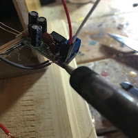
To provide that external indication, I carefully removed the LED from the receiver's circuit board and replaced it with a couple of lengths of wire that had female DuPont connectors on the end of them. I then inserted a new LED into the DuPont sockets
With the LED installed I then hooked up the speaker wires to the receiver output jacks, inserted the receiver sensor in the hole that I had drilled into the side of the cabinet and glued the receiver in place with hot glue.
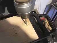
I then marked the location for the on/off switch and the power connector on the cabinet back and created the access openings for them by first drilling a pilot hole at the marked locations followed by enlarging the openings to fit with a rotary tool.
While I was there I also drilled out a 5 mm hole for the LED.
The negative wire from the receiver was then soldered to the negative connector on the power socket.
The switch, power socket and the LED were then installed into the cabinet back and secured in place with hot glue.
At this point this effectively completes the speaker build. The only thing left to do now is to install the back into the cabinet, apply some felt feet to the bottom of the speaker, plug it in and turn it on.
I am quite pleased on how things turn out - something was likely to be destined for the crusher is living a new life.














No comments:
Post a Comment