In my previous post I extolled the virtues of using "electronic LEGO" as building blocks to put together some rather complex electronics projects.
While using these electronic modules certainly have their advantages, sometimes it may just be simpler to break out the soldering iron and build your own "LEGO"
I tend to build a lot of projects that have a need to do something whenever it gets dark out, so I have a real need for a switch that has the smarts to know when it gets dark outside and yet be small, simple and reliable.
This circuit is effectively the heart of a lot of everyday items such as solar garden lights and night lights.
While I could just have simply just cannibalized an old garden light in order to have this functionality in my projects, I really was a bit curious on what made these things tick.
After doing some research, I was really quite surprised on how simple this type of circuit really was.
In it's simplest form, the brains of the operation is a photo cell that acts a variable resistor (low resistance in the daytime, high resistance when it's dark out) that is used to trigger a transistor - which is then used as a switch to turn on whatever it is you want turned on (such as a LED for a garden light, for example)
The real beauty of this is that to build this circuit, you just need a few parts:
- A 2"x2" perf board - I got mine at my local surplus store
- A Photocell - Digikey part number PDV-P8104-ND
- A 2N3904 transistor - Digikey part number 2N3904FS-ND
- A 100 Kilo Ohm resister
- Some Black and red hook up wire
 |
| Photo Cell, 3904 transistor, 100K resistor, perf board and wire |
In order to keep things as simple as possible I decided to wire the circuit components together using a "dead bug" method (where the component leads are soldered to each other).
Basically the whole circuit is made up of 3 components:
 |
| Dark activated switch circuit diagram |
 |
| 3904 transistor installed |
Once that was done, I then mounted the 100 Kilo Ohm resistor to the board and soldered one lead from the resistor to the Base lead of the transistor.
I do want to take a moment to provide a bit of a personal trick when it comes to dealing with transistors. Most transistors have 3 leads attached to them (referred to as the Collector, Base and Emitter respectively) with the body of the transistor usually encased in a piece of plastic in the shape of a half circle.
The issue with transistors is that they are not very forgiving if you happen to hook them up the wrong way. Many a brave transistor had to perish before I came up with this little trick.
Before I install a transistor in the circuit, I always make a drawing of the transistor schematic symbol and mark out the collector, base and emitter leads on the diagram. Next I make a drawing of the physical transistor itself and I also mark the leads on that diagram. By doing this, I stay crystal clear on what goes where when I install the transistor in a circuit
 |
| Identifying the leads of a transistor |
With the heart of the circuit now built, the last step is to attach the wires to supply to and send power from the circuit.
 |
| Ready to install the hook up wire |
Taking the 2 black wires next, I soldered the end of one of the wires to the emitter of the transistor. This wire will be connected to the power source for the circuit.
Next, I attached the remaining length of black hook up wire to the board and soldered the wire to the collector of the transistor. This wire will be connected to the device that the circuit will be turning on.
 |
| Wiring completed |
At this time I gave the circuit a quick test by hooking up the circuit to a battery source and attaching a LED to the output leads and then turned off the lights - the LED should should light right up. Likewise, with the lights on - the LED should go dark.
Now that things seemed to be working, I labelled the power in and power out wires with some tape.
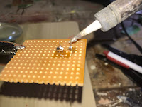
As a final step, the circuit needed a certain degree of weatherproofing since the circuit will likely be spending it's life in the great outdoors. To weatherproof the circuit, I applied a liberal covering of hot glue to the perf board and any exposed component leads.
Voila, home brewed electronic LEGO! The nice thing with this circuit is that since it contains very few parts, I usually can whip a bunch of these at a time so that I would always have some available whenever the need arises.


No comments:
Post a Comment